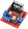
1PCS L298N Driver Board Module L298 Stepper Motor Smart Car Robot Breadboard Peltier High Power L298N DC Motor Drivers
Colore


Caratteristiche
Descrizione
Hign-concerned Chemical : None Model Number : L298N Type : Module
Origin : China Condition : New Features 1 : L298N Features 2 : driver board module Features 3 : L298 stepper motor smart car Features 4 : robot breadboard Features 5 : peltier High Power
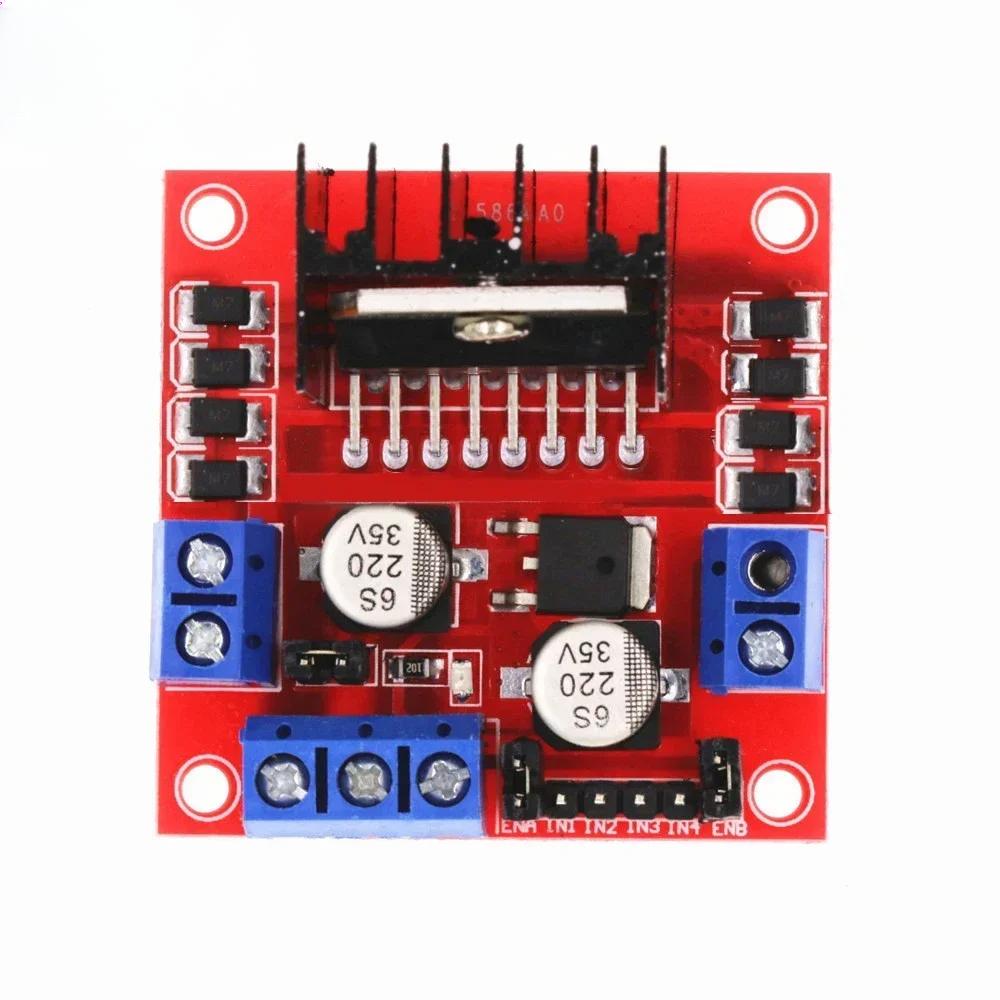
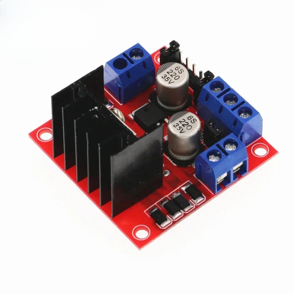
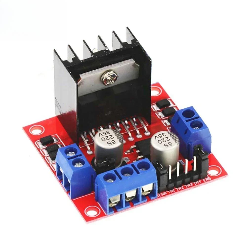
L298N Product Description:
Module name: dual H-bridge motor drive module Main control chip: L298N Logic voltage: 5V Logic current: 0mA-36mA Storage temperature: -20°C to +135°C Weight: 30g Operating mode: H-bridge drive (dual) Driving voltage: 5V-35V Driving current: 2A (MAX single bridge) Power: 25W External Dimension: 43*43*27mm Product Features:
This module uses ST's L298N as the main driver chip, which is characterized by strong driving ability, low heat generation and strong anti-interference ability.
This module can use the built-in 78M05 by driving the power supply part of the power work, but in order to avoid damage to the voltage regulator chip, when using more than 12V drive voltage, please use the external 5V logic power supply.
This module uses high-capacity filter capacitors, continuous current protection diodes, which can improve reliability. Caution:
1. When your drive voltage (the above diagram identifies 12V input, the actual acceptable input range is 7-12V) is 7V-12V, you can enable the on-board 5V logic power supply, when using the on-board 5V power supply, the interface in the +5V When the on-board 5V supply is used, the +5V supply in the interface does not need to be input, but can draw out 5V for external use. (This is a regular application!)
2. When the drive voltage is higher than 12V, less than or equal to 24V (the chip manual can support up to 35V, but according to the experience of the general 298 conservative application voltage support).
(The chip manual suggests that it can support up to 35V, but according to experience, the general 298 conservative application voltage support to 24V is already very impressive!) When, for example, to drive the rated voltage of
18V, for example, to drive a motor with a rated voltage of 18V. First, you must remove the jumper cap that enables the on-board 5V output. Then the 5V output port is externally connected to the 5V enable.
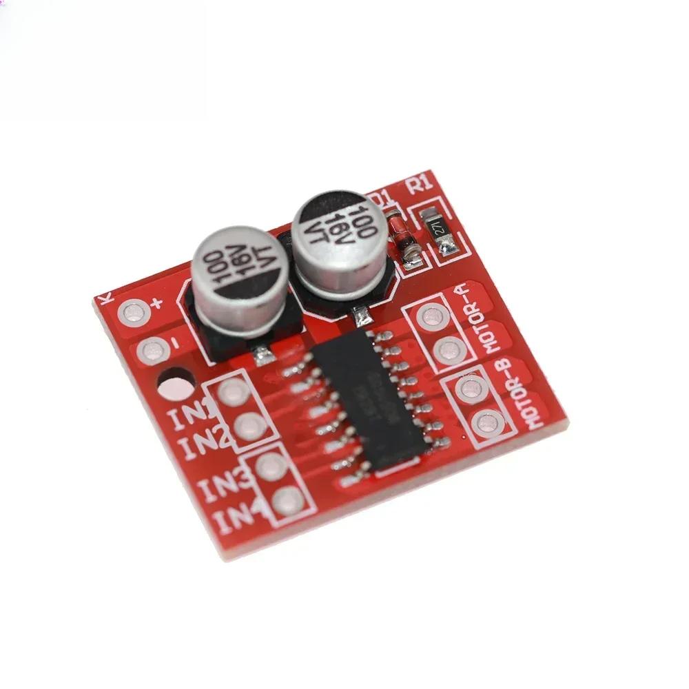
5V enable is a control signal with a level of 5V. When this signal input is valid, and the power supply in the motor driver module is normal, the motor driver module will output current. Otherwise, even if the power supply is normal, there is no current on the motor. The voltage is supplied to the internal logic circuit of L298N. (This kind is an unconventional application of high voltage drive!) Mini-L298N
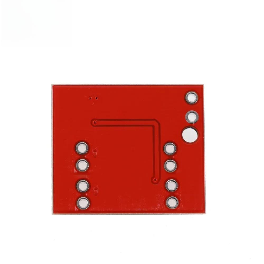
Description:
Motor drive module is very suitable for use on battery-powered smart cars, toy cars, robots, etc., supply voltage 2V ~ 10V, can drive two DC motors or a 4-wire, 2-phase stepper motors at the same time, can be realized in the forward and reverse and speed functions, the current of each circuit can be up to 1.5A sustained current, the peak current of up to 2.5A, with thermal protection and can be automatically restored. Product Parameters:
1、Dual-circuit H-bridge motor drive, can drive two DC motors or one 4-wire two-phase stepping motor at the same time; 2, module power supply voltage 2V-10V. 3, Signal terminal input voltage 1.8-7V; 4, single-channel operating current 1.5A, peak current up to 2.5A, low standby current (less than 0.1uA); 5、Built-in anti-common-state conduction circuit, the motor will not be inadvertently operated when the input is suspended; 6、Built-in thermal protection circuit (TSD) with hysteresis effect, no need to worry about the motor jamming Precautions:
1. Reversing the positive and negative poles of the power supply will definitely cause circuit damage.
2. Output to ground short circuit or short circuit output, as well as motor blocking, the chip will be thermally protected, but in the case of close to or more than 10V voltage and the peak current is much more than 2.5A will also cause the chip burned.
The line layout is compact and regular, with good electrical insulation and mechanical stability, and can maintain stable performance under different temperature and humidity environments to ensure accuracy and reliability.
In circuit design, carefully planned lines are like precision transportation networks, and lines of different widths and spacings undertake different currents and signals transmission tasks respectively. The key signal lines are impedance matching processing, which greatly reduces signal reflection and attenuation and ensures the stable transmission of high-frequency signals.
All kinds of electronic components are soldered on the circuit board, and the solder joints are full, round, and firm and reliable. Core components like chips are perfectly connected to the circuit board through fine packaging processes to achieve high-speed data processing and interaction.
This circuit board has a wide range of responses in many fields. Whether in the industrial control field that requires extremely high stability or consumer electronics field that pursues extreme performance, it can provide solid guarantees for the stable operation of the equipment with its excellent design and reliable performance, and help various electronic devices play a powerful role.